You may have heard the term chip, a chip is a tiny piece of silicon, usually around one centimeter square. It can be an integrated circuit composed of many interconnected transistors. A chip may be a single transistor. There are two basic types of integrated circuit — monolithic and hybrid. Monolithic ICs include the entire circuit on a single silicon chip. A hybrid IC has a circuit with several chips enclosed in a single package. The chips in a hybrid IC may be a combination of transistors, resistors, capacitors and monolithic IC chips.
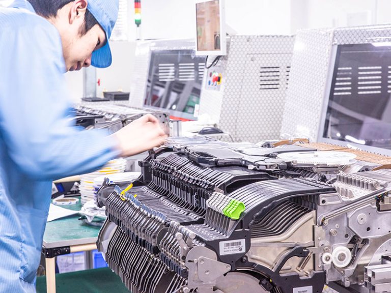
A printed circuit board, or PCB, holds an electronic circuit together. The completed PCB with components attached is a printed circuit board assembly, or PCBA. A multi-layer PCB may have as many as 10 stacked PCBs. Electroplated copper conductors passing through holes called vias connect the individual PCBs, which forms a three-dimensional electronic circuit.
The most important elements in an electronic circuit are the transistors. Diodes are tiny chips of silicon that act as valves to allow current flow in only one direction. Resistors offer a specified amount of resistance to current, and capacitors store electric charge. Other electronic components are passive elements like resistors and capacitors. The third basic passive circuit element is the inductor, which stores energy in the form of a magnetic field. Microelectronic circuits very rarely use inductors, but they are common in larger power circuits.
Most circuits are designed using computer-aided design programs, or CAD. The circuit designer starts with a general specification for the functioning of the circuit, and the CAD program lays out the complex pattern of interconnections. Many of the circuits used in digital computers are extremely complex and use millions of transistors, so CADs are the only practical way to design them.
The exposed metal is etched away, leaving the pattern of connecting metal between components. The etching of the metal interconnection pattern on a PCB or IC chip uses an etch-resistant masking layer to define the circuit pattern.
FR-4 glass epoxy is the most common insulating substrate. Another substrate material is cotton paper impregnated with phenol resin, often tan or brown.
When a PCB has no components installed, it is less ambiguously called a printed wiring board (PWB) or etched wiring board. However, the term “printed wiring board” has fallen into disuse. A PCB populated with electronic components is called a printed circuit assembly (PCA), printed circuit board assembly or PCB assembly (PCBA). In informal usage, the term “printed circuit board” most commonly means “printed circuit assembly” (with components).
Circuit properties of the PCB Edit
Each trace consists of a flat, narrow part of the copper foil that remains after etching. Power and ground traces may need to be wider than signal traces. Its resistance, determined by its width, thickness, and length, must be sufficiently low for the current the conductor will carry. In a multi-layer board one entire layer may be mostly solid copper to act as a ground plane for shielding and power return. For microwave circuits, transmission lines can be laid out in a planar form such as strip line or micro strip with carefully controlled dimensions to assure a consistent impedance. In radio-frequency and fast switching circuits the inductance and capacitance of the printed circuit board conductors become significant circuit elements, usually undesired; conversely, they can be used as a deliberate part of the circuit design, as in distributed element filters, antennae, and fuses, obviating the need for additional discrete components.


-768x576.jpg)
