
Designing 5G systems is all about high speed/high frequency mixed signal design. In addition to standard high speed design rules and high frequency layout rules, material selection is an important part of preventing signal losses and ensuring signal integrity. As these systems are inherently mixed signal, designers must prevent EMI between analog and digital board sections, as well as design their boards to meet FCC EMC requirements.
In anticipation of the coming 5G revolution, PCB materials companies are already developing substrate materials with lower dielectric constant (around 3) than that of standard FR4. Despite the higher frequency, these newer materials have less loss at 5G wireless frequencies compared to PTFE laminates.
PCBs for 5G systems will require processors and power amplifiers that operate at high speed and high frequency, and variations in the output from these components can be minimized with effective thermal management. Two material properties that are of interest in 5G systems are the thermal conductivity and thermal coefficient of, which measures changes in the dielectric constant of the substrate with temperature. The heat generated by circuit operation or by ICs can lead to temperature rise which would cause the loss of dielectric performance gradually.
The importance of the first parameter should be obvious: a substrate with higher thermal conductivity easily dissipates heat away from an active device, and a substrate with higher thermal conductivity is a better choice when working at higher speed and higher frequency. The importance of the second parameter may not be so obvious. Variations in the dielectric constant can induce dispersion along an interconnect, and severe dispersion will stretch digital pulses, change the propagation speed along an interconnect, and lead to signal reflections along a transmission line in extreme cases.
No matter which substrate material you opt to use in your 5G system, you’ll need to follow best PCB design practices ensuring consistent impedance throughout interconnects. With RF signal lines, traces should be routed using the shortest possible path. Conductor widths and spacing also require tight control in order to maintain consistent impedance throughout interconnects.
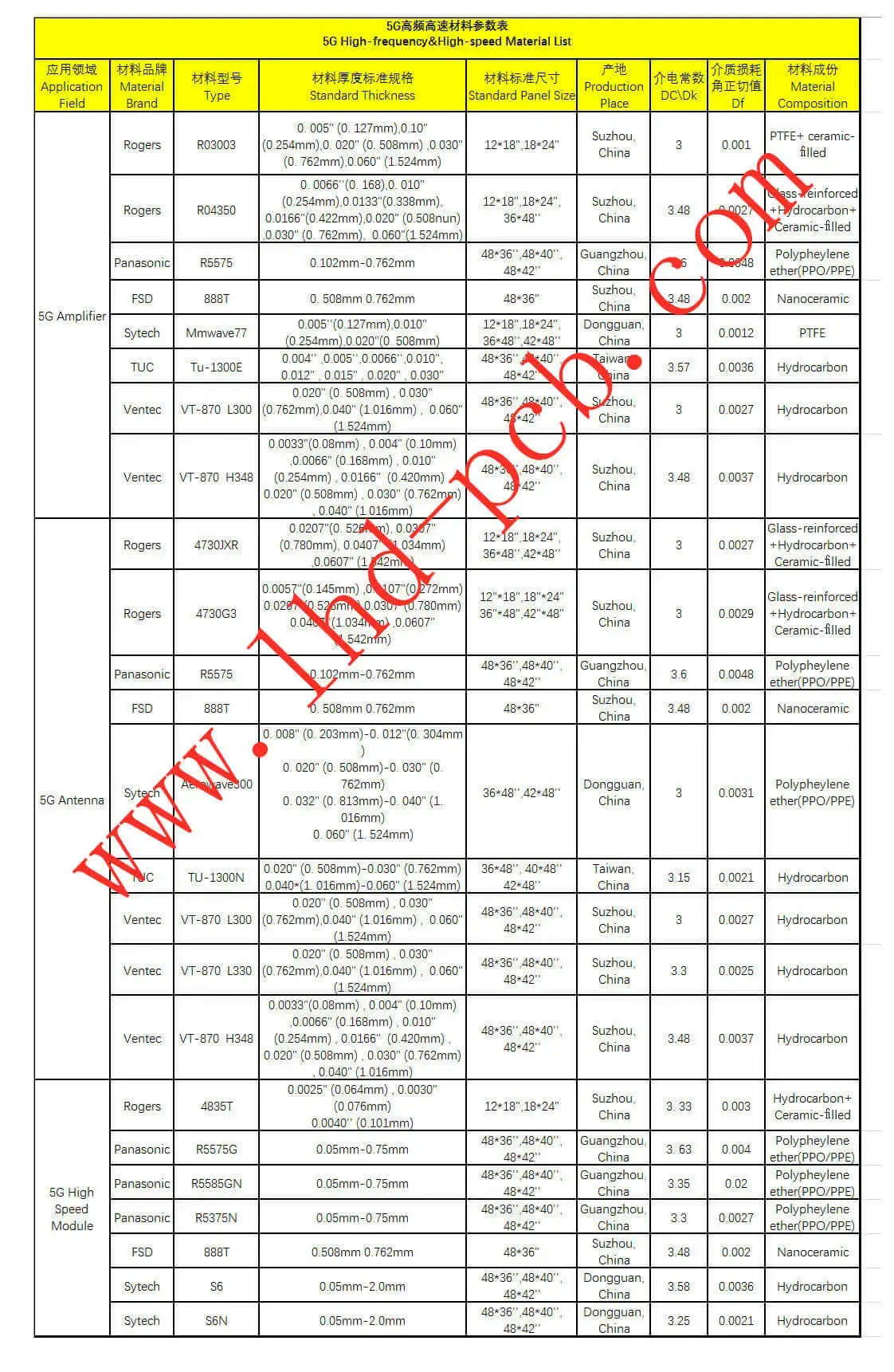
Below is a picture of 5G High-frequency&High-speed Material List, you can make it as a reference when you design the 5G PCB.
Ultimately, 5G will drive broader adoption of AR/VR, networking among autonomous vehicles, new smart devices, and other applications we can only dream of.
-768x513.jpg)
-768x576.jpg)